Yagi Basics
In essence, a “Yagi” antenna has 4 parts:
- The Boom – This is the center piece in which you mount the other elements.
- The “driven element”, which I like to refer to as the “driver”.
- The “reflector”.
- The “directors”.
The boom typically is of a little heavier material. It is used to spread out the other elements and mount elements upon.
The “driven element” is usually set for a specific length usable on certain bands of frequencies.
The “reflector” is 5% longer than the driver, has contact with the ground element of the system (coax shield for instance) and may be directly attached to a conductive boom (or non conductive boom, whatever the case may be).
The “directors” work in conjunction with the driver but are not directly electrically connected but are theoretically RF conductive. The director, theoretically, will enhance the output of the Yagi by multiplying the output of the driver. The directors are insulated from ground and insulated from a conductive boom (which is grounded to the feed line shield or ground leg of a ladder line).
What I have described above is a simple “three element” Yagi, plus a boom. “Elements” are defined as the being the antenna itself, but one must not forget the boom. It comes into play, especially if the antenna is designed with a common ground among the boom and reflector.
The basic RF antenna as you are fully aware, is a half-wave di-pole antenna. A Yagi works similar to a di-pole because the driver is basically a di-pole, but the length may vary and usually does, especially when you’re building a multiple-band version of a Yagi.
While mono-band Yagis exist and in fact, some people prefer them, what I am explaining in this page is a multi-band di-pole.
Working with multi-band di-poles and using an antenna analyzer to check my math, just doesn’t work out for me. Perhaps I don’t have the experience or knowledge to work out the details between the analyzer and the math. I am not sure. However, I have yet to see an analyzer (specifically on HF) give me confidence in a multi-band antenna, homebrew or otherwise, if the math is correct. Therefore, I have come to terms with this and understand that even if the antenna analyzer doesn’t return the expected results on a given antenna, if I place my confidence in math (which everyone should), the antenna will work (proven time and time again to me). I trust math. I trust my abilities to do the math. It’s really not that hard to do and is easily accomplished through a variety of online forms that deal with antenna calculations, including the form on this site.
The reason I was prompted to write this article is several-fold. First, I purchased a bunch of aluminum yesterday at the Charleston Area HamFest. I said “bunch of aluminum” because while each of the 4 conglomerations appeared to be “antennas”, once I began looking at them more closely, I found out that the guy that mangled three of them together didn’t have a F’in clue what he was doing. He had the skills necessary to put together sturdy antennas. All of the parts were there, pretty much. However, when he looked at the plans for his homebrew, he was either led astray by an even bigger moron or he simply didn’t pay attention to the details. Most people wouldn’t make a big deal of this, heck, most people wouldn’t even say anything about it. I like to refer to this as being a “teaching moment”. We’ll all learn something from this guy’s mistakes. Good thing I didn’t spend much money on all of this aluminum, and trust me, I bought a lot of stuff from this guy for not a lot of money.
I’ll try to explain what happened with three of the four Yagis I purchased with a series of pictures:
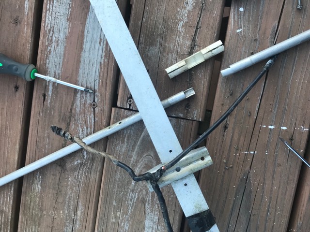
This was the “end” of the coax, each leg of the “wye” was shoved into the driver tube. Neither end was soldered to the tube. The feedline coax coming to the “wye” was soldered, each leg, to the shield of the right and left portion of the “wye”. At the ends of the “wye”, the shield was then soldered to the center conductor. The center conductor was electrically connected to the other end of the “wye” and back down to the feedline. Again, neither end of the “wye” was soldered to the Yagi. He was basically using this coax “wye” as an antenna and the Yagi did NOTHING for him truthfully, but may have had a slight increase in propagation based on RF radiation to the driver and the director.
This is a picture perfect example of what not to do. All of the work he put into building the Yagi went for naught. He lost any advantage of having a Yagi by wrapping it around a coax antenna and not connecting the feedline to either the driver nor the grounding. He never even had the advantage of better reception or directional reception because of this.
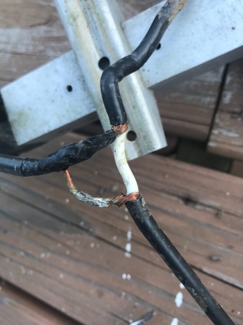
Here’s a little better view of the feedline (left) coming into the “wye” and the electrical connections. You can see the shield of the “wye” (top/center) being connected to the center conductor of the feedline and the split shield of the bottom half of the “wye” being connected electrically to the shield of the field line (bottom/center). At each end (see below), the ends of the wye, left and right” were soldered together.
And below, is the ends of the “wye”.
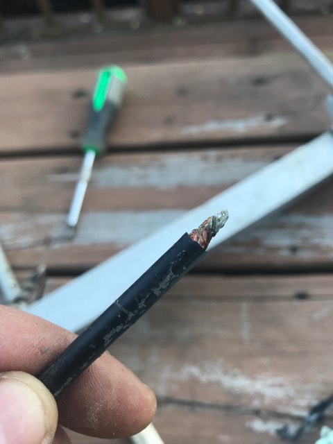
The ends of the “wye”, soldered together and making a coax antenna. The ends were wrapped with electrical tape and made no electrical connection the Yagi.
The fourth Yagi I purchased from the same guy appears to be a factory made (yet to be determined the manufacturer or model, I’ll update this when I find out) Yagi, supposedly a “tri band” 10m, 15m & 20m 6 element antenna. Almost everything was in a box of stuff to put the antenna together and so far, I have taken the driver apart, fixed the feedline connection and have it in the air on a 10ft piece of conduit, by itself and I’ve been able to use my LDG AT-600Pro II auto tuner to tune 80, 40, 20, 17, 15, and 10 meters. How does it propagate on all of those bands? Probably not well on 80, 40 and 17. But it tunes. Which means I can use it. I’ll probably stick to 20, 15, and 10, which I suspect is what it’s designed for.
Ok, so I’ve explained what prompted me to write this page.
Now then, about the analyzer. Again, maybe it’s my lack of knowledge or experience, but I put the driver on the analyzer and scanned the bands to see what the analyzer thought the antenna was good for. What the analyzer said was it was resonant on 108Mhz, which is great, if I were trying to create a pirate FM broadcast station (well, that’s a thought). But no, the analyzer did not show it being anywhere compatible (over a 10:1 SWR) with 10, 15 or 20m. I thought, why trust an analyzer now? I’ve not trusted one in the past 4 years and have had a perfect record with my math and good propagation from my creations, so let’s hook it up and see what happens.
It tuned.
What I don’t know, may not hurt me.
I’ve done a bit of research on various Yagi designs. I’ve seen a few, but of course, I am no expert my any means. I’ve put up a few, worked on a few, and otherwise played around with a few. Again, not an engineer, but a little experience. Something I’ve noticed, there’s some plans for homebrew “Yagi” antennas that I don’t really think qualify, just like the 3 of 4 I purchased. The fourth I purchased, as mentioned above as being what I thought was a “factory” antenna, doesn’t really appear to be such. Today, I decided to fool around a bit with it. I took the driver, redid the ring connectors on the coax, put it on a piece of mast pipe and did some testing. I decided to do a bit more research and found out that it “appears” to be an older TET Yagi, but not exactly. Parts of it appear to be from a TET, parts appear to be from other antennas, so I think it was cobbled together from parts, probably from the same guy that cobbled the other antennas together. The good part about it is, I believe everything I need to make a decent Yagi antenna is there, except the boom. The guy I bought it from seems to want to condense things a little on the extreme side. His boom is about 1/4 the size of the shortest boom you should use for a six element yagi. So, why did he have all of those extra directors in there, if he wasn’t using them? Spares? Also, there’s no insulators for the directors. Which brings me to another discussion point:
I’ve had discussions with several people that have mentioned everything except the driver being affixed directly to the metal boom. Now here’s where my inexperience may help or hurt me. Now, I dunno about the exact engineering involved, but it just makes sense to me, if the directors are at the same potential (ground) as the boom and reflector, and electrically connected to the coax ground, it just seems to me that the directors would be shunting any RF to ground, when by design, they’re suppose to effectively enhance the RF (slightly) in the direction of the next director, and so on, as long as the directors are all the same length at 5% less than the driver. (There is of course a lot more to the theory on this, which is freely available on the interswebs). Now, on the receive side, more elements would be attached to the shield side, the better the reception and I would suspect a reverse of the forward directing would occur, enhancing the receive, even slightly. Remember, 3db gain out effectively doubles the radiated power. Reverse gain increases the received signal strength, hence, why a beam works the way a beam works.
Now, I’ve had a look at a few beams, some of which appear to not be Yagis (like those that I have purchased) and they should not perform like a Yagi. I’ve been looking through manuals and images today and see many that have the directors insulated and the reflector and booms are grounded. Within the coming weeks, I’ll be building a homebrew on this type of design. Only thing I can say right now is, only time will tell.
I spent about 2 hours this evening doing a lot of research. What I’ve found is, the guy that built (cobbled) the multiband HF yagi on a design that required a gamma-match, but did not add the gamma-match. That being said, after spending all of this time researching this issue, I’ve come to see that there are two different camps regarding Yagis, those that believe in gamma-matched Yagis for HF (who also think that non-gamma-match is for VHF or above) and those that don’t think gamma-matched is either necessary or not always necessary.
Here’s the website of what appears to be a Guru of Yagis: https://www.g0ksc.co.uk/index.php
More later. Time for bed.
Next up: Gamma Matched or Non-Gamma Matched.
73!
N8GB